M-HC218
Data:
M-HC218 versions: 15 different intensification factors
PIN: 20–207 bar
PH: 800 bar maximum
PRETURN: As low as possible (return pressure to tank)
POUTLET: PH = (PIN – PRETURN) x intensification factor
Mounting: Inline tube
Weight: 5.6 kg.
Description
The M-HC218 is a compact unit weighing only 5.6 kg. It is ideal for use in a variety of applications where building and maintaining high pressure is required.
The M-HC218 incorporates an adjustable pressure relief valve on the high pressure side. The pressure relief valve controls the maximum allowable pressure the system can output, allowing the booster to go for a higher end pressure producing flow at the decided pressure.
The M-HC218 also incorporates manual directional valve (DCV) to control inlet pressure to the booster section. Solenoid valves are also available on request.
The M-HC218 raises supplied pressure to a higher outlet pressure and automatically compensates for consumption of oil to maintain the high pressure. Adjustment of the outlet pressure is carried out by varying the supplied pressure.
An optional orifice can be mounted in both IN- and R-ports of the booster to prevent overspeeding.
Flow rates
| Intensification factor i | Max. intensified outlet flow l/min | Max. inlet flow l/min |
|---|---|---|
| 1.2 | 3.5 | 40.0 |
| 1.5 | 4.2 | 40.0 |
| 2.0 | 3.2 | 40.0 |
| 2.2 | 2.9 | 40.0 |
| 2.5 | 2.7 | 40.0 |
| 2.8 | 2.5 | 40.0 |
| 3.2 | 2.5 | 40.0 |
| 4.0 | 2.0 | 40.0 |
| 5.0 | 1.6 | 40.0 |
| 6.6 | 1.3 | 40.0 |
| 9.0 | 0.9 | 40.0 |
| 13.0 | 0.6 | 40.0 |
| 16.0 | 0.5 | 40.0 |
| 20.0 | 0.3 | 40.0 |
| 25.0 | 0.2 | 40.0 |
Functions
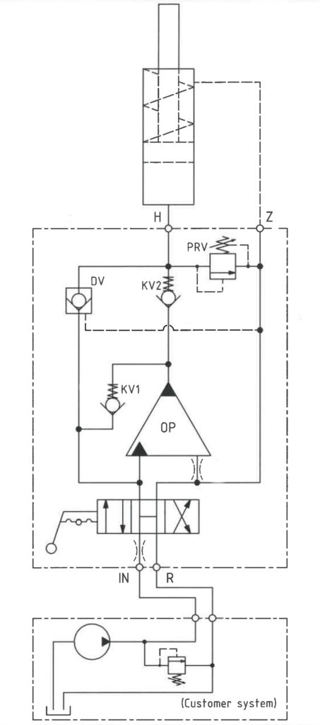
The basic operation is illustrated in the function diagram. Oil is fed through the directional valve CV to the IN port, flowing freely through the check valves KV1, KV2 and DV to the high-pressure side H. In this condition maximum flow through the booster is achieved giving a fast-forward function.
When pump pressure is reached on the high-pressure side H, valves KV1, KV2 and DV will close. The end pressure will be achieved by the oscillating pump unit OP. The unit will automatically stall when end pressure on the high-pressure side H is reached. If a pressure drop on the high-pressure side exists due to consumption or leakage, the OP valve will automatically operate to maintain the end pressure.
A relief valve is installed to control the maximum allowable pressure the system can output, allowing the booster to go for a higher end pressure producing flow at the decided pressure.
Function diagram
111-00
Dimensions
Dimension drawing M-HC218-00
Connection types
| Connection | IN / R / Z | H |
|---|---|---|
| 1 | 1/4" BSPP | 1/4" BSPP |
Adapter Drawing
Adapter ordering codes and specifications are shown in the PDF-file: 2-901-01
Fluids and materials
Additional information is available on the website under Products → General specifications.
Ordering an M-HC218
Ordering example of an M-HC218 with i = 4.0 DV incorporated and BSPP connections: M-HC218 – 4.0 – B – 1
Attention note!
Valve pre-setting is required, please specify when ordering the intensifier.
If connection adapters are required, please specify ordering code . See adapter table.
Adapters will be factory mounted.
Model
- M-HC218
Intensification, i
- Select factor
- See flow rate table
Model version
- Select type
- A = without DV
- B = with DV
Connections
- Select thread
- 1 = BSPP
Max. tightening torque BSPP
| IN / R | H | |
|---|---|---|
| 1/4" BSPP | 1/4" BSPP | |
| with steel washer | 4.0 da/Nm | 4.0 da/Nm |
| with cutting edge | 4.0 da/Nm | 4.0 da/Nm |
miniBOOSTER Hydraulics A/S
Fynsgade 3
DK - 6400 Sønderborg
Tel: +4574429292
Fax: +4574424204
info@minibooster.com
Monday-Friday: 8AM -5PM
(GMT +1)