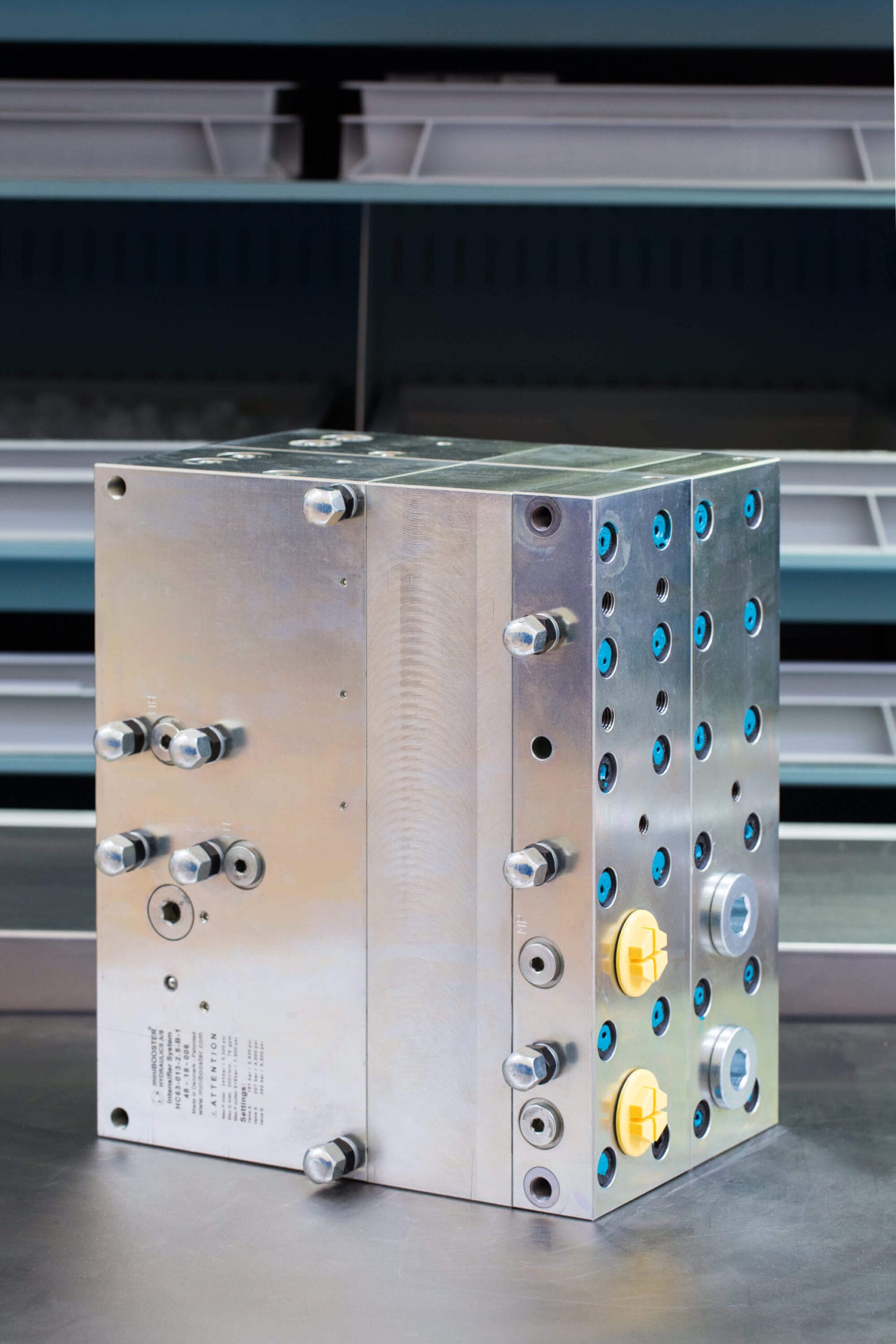
HC63-013
Key features:
Automatically activated (sequence valve)
High pressure – up to 800 bar (11,600 psi)
Fast fill – system flows up to 300 l/min
Max. inlet pressure = 345 bar
Adjustable outlet pressure
Extended service life
Robust design
Flexible design; several boosters/intensification ratios
Switch from by-pass to intensified flow
Mounting: Inline tube or flanged
Weight: 55.0 kg.
Description
HC63-013 In-line Intensifier System is designed to boost the hydraulic pressure from the pump to the workload. It operates only when needed, to save energy. The system is dynamical by means of being able to provide flow at high pressure.
Typical applications
Mobile attachments; motors – steering systems – cutters – crushers – shears, off highway equipment, injection molding machines and hydraulic presses. Applicable to machines with insufficient pump capacity to prevent machine stoppage when peak pressures occur.
Easy installation
HC63-013 is provided with four mounting holes for through bolt installation. The four connection ports are placed logically in pairs and in line of each other on the HIC block. All surfaces are electroplated for good protection and fine surface finish.
HP flange mounting is optional. Furthermore, it is possible to flange multiple HC63-013 intensifier systems in order to achieve higher flow.
Flow rates
| Intensification factor i | Max. intensified outlet flow l/min | Max. by-pass pump flow l/min |
|---|---|---|
| 1.2 | 64.5 | 300 |
| 1.5 | 55.5 | 300 |
| 2.0 | 48.0 | 300 |
| 2.5 | 39.0 | 300 |
| 3.3 | 33.0 | 300 |
| 4.0 | 27.0 | 300 |
| 4.9 | 21.0 | 300 |
| 6.3 | 16.5 | 300 |
| 8.2 | 13.5 | 300 |
Functions
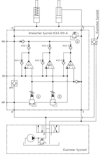
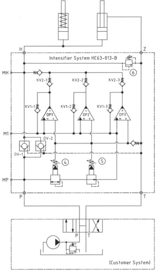
The function of the system is simple, but smart. The hydraulic oil is by-passed directly from the pump to the workload at maximum flow when back pressure from the workload has reached a set point close to the maximum pressure of pump.
A sequence valve opens and directs the oil to the booster, which makes the pressure rise. The shift between maximum pump pressure and high pressure happens without intervention from the user and ensures that the workload at all times will be driven at a maximum speed in relation to the required high pressure.
A relief valve is installed to control the maximum allowable pressure the system can output, allowing the booster to go for a higher end pressure producing flow at the decided pressure.
Function diagram A-model
63-013-A-01

Function diagram B-model
63-013-B-01

Dimensions
Dimension drawing 63-013-120-01
Connection types
| Connection | P / T / Z | H |
|---|---|---|
| 1 | 1" BSPP | 1" BSPP |
| 1 | 1" BSPP | Flange mounting |
Flange mounting
Flange mounting drawing 62-120-F
Fluids and materials
Additional information is available on the website under Products → General specifications.
Ordering an HC63-013
Ordering example of an HC63-013 with i = 4.0, DV incorporated and BSPP connections: HC63 – 013 – 4.0 – B – 1
Attention note!
The G-model is available in 2 variants, when ordering please specify accordingly:
- Dynamic – low hysteresis: Ordering example of an HC63-013 with i = 4.0 RV incorporated and BSPP connections: HC63-013 – 4.0 – G – 1
- Fail safe – high hysteresis: The RV valve opening ratio is to be determined on individual basis. Contact our technical support. Ordering example of an HC63-013 with i = 4.0 RV with opening ratio x.x incorporated and BSPP connections: HC63-013 – 4.0 – G – x.x – 1
Model
- HC63-013
Intensification, i
- Select factor
- See flow rate table
Model version
- Select type
- A = without DV
- B = with DV
- G = with proportional valve
Connections
- Select thread
- 1 = BSPP
Selection of intensification factor
The intensification factor depends on available inlet and desired outlet pressure. To calculate the initial factor, please use the following formular:
i = Desired high pressure / Pump pressure
Desired pressure: 500 bar
Pump pressure: 200 bar
i = 500 / 200 = 2.5
For static use: Select an intensification factor higher or equal to the calculated value. In this case i = 2.5, the desired pressure of 500 bar is finally adjusted with the HP relief valve.
For dynamic use: Select an intensification factor 60% higher than the calculated value. In this case i = 500 / 200 = 2.5 + 60% = 4.0, the desired pressure of 500 bar is finally adjusted with the HP relief valve.
Adjust the pressure-reducing valve to reach a pressure 40% higher than the settings at the relief valve. In this case 500 + 40% = 700 bar.
Max. tightening torque
| P / T | H / Z | |
|---|---|---|
| 1" BSPP | 1" BSPP | |
| with steel washer | 33.0 da/Nm | 33.0 da/Nm |
| with cutting edge | 33.0 da/Nm | 33.0 da/Nm |
Max. tightening torque flange mounting
| Mounting bolt | ||
|---|---|---|
| M10 8.8 | 5.0 da/Nm |
