High flow – low pressure • Low flow – high pressure
As shown on the chart, miniBOOSTER has a dual flow/pressure feature. Initially, when fluid is supplied to the booster, it flows straight through to the high- pressure side. At this point, all the supplied flow, up to the max. allowed inlet flow, goes to the actuator allowing it to operate fast in the desired direction. As soon as inlet pressure is reached in the actuator, the flow will then be supplied via the high-pressure piston until intensified pressure is reached.
Temperature range oil: -40 °C to +120 °C
Temperature range water: +3 °C to +50 °C
Inlet pressure: Min. 20 bar (290 psi), max. 207 bar (3000 psi)
Outlet pressure: See performance data for each model
Maximum inlet flow: See performance data for each model
Connections: See data for each model
Filtration: 10 micron nominal; max. 19/16 according to ISO 4406
| Media | ISO target levels 0 to 140 bar | Micron ratings | ISO target levels 141 to 207 bar | Micron ratings | ISO target levels | Micron ratings | |
|---|---|---|---|---|---|---|---|
| Oil | > 5 cSt | 19/17/14 | 10 | 18/16/13 | 5 | 17/15/12 | 3 |
| Water / Water Glycol | < 5 cSt | 18/16/13 | 5 | 17/15/12 | 3 | 16/14/11 | 3 |
Advantages:
- Gives high pressure whenever needed
- Expensive high-pressure pumps not required
- Expense saved on tubing
- Increase expensive high pressure by simply increasing inexpensive low pressure
- Low pressure is changed into high pressure with hardly any use of energy or heat generation
- Leakages on the high-pressure side compensated dynamically
- System works with labyrinthine tubing, which gives a longer life
- No rotating parts
- Light weight
- Small size – high performance
Typical clamping circuit
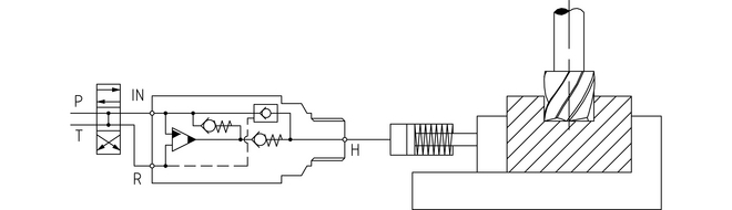
0-103 Model – Example with single-acting cylinder
The HC2 is used to boost the pressure in an existing hydraulic circuit, e.g. in a machining centre to ensure a sufficient clamping force. As the HC2 can be directly fitted into the workholding system, high-pressure connections can be avoided.
Applications with larger flowrates
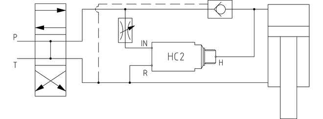
10-104 Model – Example with external pilot-operated check valve
In applications where the pump supplies a flow exceeding the maximum permissible supplied flow to the HC2, the HC2 is installed in parallel with a pilot-operated check valve. This check valve is dimensioned to allow for all the flow supplied from the pump. The inlet flow to the HC2 is limited to the maximum permissible flow for the particular intensification ratio.
As the cylinder moves forward, all the flow from the pump is used. When the pump pressure is established in the cylinder the check valve closes, and the end pressure builds up through the HC2. The cylinder is retracted by changing the position of the directional valve, whereby the pump is connected to the other side of the cylinder and the DV opens, allowing the fluid to return to the tank.
Fluids
- Recognised hydraulic and transmission fluids compatible with Buna-N seals
- Viscosity 1 to 500 cSt (mm2/s)
- Water glycol mix (minimum 5% Glycol)
- Other media on request
- For other fluids, contact technical sales
Materials
- Oil boosters: Body: cast iron, internal components: steel, external surface: zinc chromate finish
- Stainless boosters: Body and internal components: stainless steel 316L W.1.4404
- Static seals: nitrile – other material on request, e.g. Viton, EPDM
- Dynamic seals for dual media boosters: see table below
| Material code | Description | |
|---|---|---|
| HH | H-PUR (Polyurethan) material for both media 1 and media 2. Standard seals for up to 1,380 bar. These seals are applicable for most medias, e.g. mineral oil and seawater. | |
| HE | H-PUR (Polyurethan) material for media 1 and EPDM material for media 2. Seals for e.g media 1 mineral oil and media 2 Skydrol, EPDM swells up if exposed to mineral oil. | |
| HP | H-PUR (Polyurethan) material for media 1 and PEEK material for media 2. Seals for applications with pressure higher than 1,380 bar and/or extremely aggressive media 2. |
miniBOOSTER Hydraulics A/S
Fynsgade 3
DK - 6400 Sønderborg
Tel: +4574429292
Fax: +4574424204
info@minibooster.com
Monday-Friday: 8AM -5PM
(GMT +1)